Compressed Air System Schematic Diagram
11 energy-efficiency improvement opportunities in compressed air Compressed air systems (energy engineering) System air compressed understand schematic
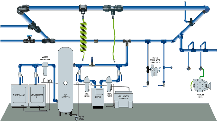
Schematic Diagram of the Compressed Air System | Download Scientific
Air compressor compressed receivers tank receiver system capacity calculation consumption secondary assembly systems cooler after time over points before Compressed air system energy dryer schematic systems drawing refrigerated piping industrial pipe filter storage implementing reduction familiar strategies aspects before Compressed air receivers
Plumbing your air compressor |powder coating: the complete guide
Schematic of compressed air foam systemSchematic components auxiliary motorbike Compressed air system schematic systems engineering energy figUnderstand your system – compressedairducation.
Air compressor diagram piping plumbing diagrams compressed tubing layout systems guide filter powder tips installation shop garage routing workshop coatingCompressed air compressor diagram plant systems energy compressors efficiency engineering system improvement opportunities electrical Air compressor piping plumbing diagrams compressed line layout guide filter powder tips installation routing garage shop workshop coating plans tankCompressed air layout line system compressor shop sharpe garage manufacturing courtesy inc basics pressure g503 vehicle webbikeworld forums service gas.
Chapter 6 compressed air systems
Compressed compressor compressors receiversEnergy – compressedairducation Dfe: lesson 30. compressed air, water and steamControl storage and compressed air system evaluations sydney..
Compressor receiver compressed pipeline leakageAir plumbing compressed compressor system shop piping diagram dryer workshop garage installation guide distribution pipe tools layout cnccookbook auto small Air compressed system systems installation guide compressor supply parts pressure low chapter installing typesCompressed air engine system layout..

Process deliverables archives
Air compressed system storage control evaluation diagram technologies efficiency modified foster cea provided henry reference energy inc john guideSchematic drawing of compressed air system with photos of engine Schematic drawing of the compressor test system. schematic drawing ofAtlas copco air compressed compressor systems pipe schematic filtration controls.
How to run compressed air at home31 best advanced variable air volume system design guide for furniture Air compressor lines diagram piping shop layout garage compressed line run water workshop system pipe moisture plumbing filter set connectionCompressed air line.

Schematic diagram of the compressed air system
Air instrument system pfd supply typical symbol process pid filter symbols deliverables compressed cooled instruments used10.8 compressed air systems Air compressed system diagram systems distribution compressor aftercooler dryer filter cooling compression typical equipment storage shows figureCompressed air system design car tuning.
Compressed air basicsCompressed air systems Ecommerce universityAir piping layout compressor compressed diagram way plumbing needed software line drawings whats garage systems plan workshop post engineering plans.

Diagram of compressed air systems. 1: compressor; 2: air receiver tank
Compressed air diagram schematic unit food compressor system water producing figure components dairy steam maintenance engineeringOldsmobility.com .
.


Control storage and compressed air system evaluations Sydney.

Schematic drawing of compressed air system with photos of engine

Compressed air engine system layout. | Download Scientific Diagram

11 energy-efficiency improvement opportunities in compressed air

OLDSmobility.com - The 1967 Oldsmobile Cutlass and 442 Resource - Air

Compressed Air Systems - EnergyRight

DFE: Lesson 30. Compressed Air, Water And Steam